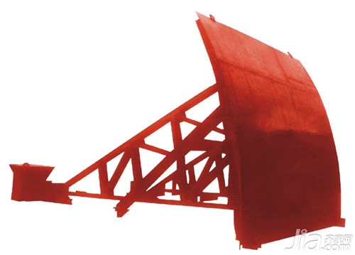
Forward curved steel gates are compared to flat gates. The arc gate has an arc-shaped water blocking leaf, and when the gate is opened and closed, the gate rotates around a horizontal axis of a fixed support hinge. Since the center of the hinge axis is generally arranged at the center of the arc-shaped panel, all the water pressure acting on the panel passes through the centroid. When the door is opened, it is only necessary to overcome the dead weight of the gate and the frictional resistance of the water stop and the hinge shaft against the axis. . The radial gate has the advantages of opening and closing effort, reliable operation, good drainage conditions, and can meet the needs of various types of drainage holes. Therefore, the arc gate is one of the priority gate types in the selection of the scheme. Here I just take a curved steel gate at understanding the production process, arc steel gate installation and commissioning of related presentations it!
The advantages and disadvantages of curved steel gates
First, the advantages
1) According to the needs of the project, the size of the orifice can be closed considerably;
2) The thickness of the pier is small;
3) There is no door slot affecting the flow state of the water, and the sediment is in good condition for a long time;
4) The opening and closing force is small;
5) The number of buried parts is small.
Second, the shortcomings
1) need more than K's gate pier;
2) The space occupied by the gate is larger;
3) Work gates can not be repaired and maintained outside the orifices, nor can they be exchanged between orifices; nature, high requirements for civil structures.
Structure arrangement and form of curved steel gate
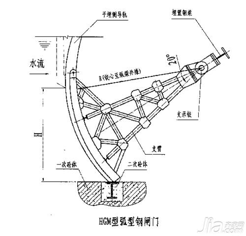
Supporting hinge position and arc radius
The support hinge of the curved steel gate is the most important component of the entire gate. In addition to the total water pressure and some of the gates re-transmitting the gate to the support, it is also the support center for the opening and closing of the gate. The position of the support hinge has a great influence on the size of the door opening force and the reliability of the gate work. In the open top radial gates, the support hinges are placed on the side of the piers in such a way that they will not be blocked by sediment and subjected to the impact of the floating objects in order to facilitate maintenance and repair. The radial gates on the river sluice and support hinges may be located higher than the flood check point downstream. 5m). The higher the position of the hinge, the longer the arc surface, the greater the water pressure, the more steel is consumed, so in the case of meeting the impact of no floating objects, the height of the hinge should be set at 1/2. Department official. Of course, the higher the position of the hinge, the more favorable to the adjustment of the stress on the base plate of the soft base. In overflow dams, the support hinges can be placed on the threshold due to the sudden drop of the water surface downstream of the gate. For submersible radial gates, the position of the support hinge is generally arranged at a height of 1.1 times the gate height.
The arc radius R is determined by the gate height H and the position of the support hinges. The open gate gate generally uses the ruler=(1.o~1.5). The larger the value is, the longer the arm is, the corresponding gate pier is also The longer, the opening and closing force can be reduced, the general submerged gate gate / c = (L1 ~ 2.2) H, when only close to / /, although the opening and closing force may increase, but the town to improve the stability of the arm and Reduce the pier length. According to domestic and international data studies, the radial radius R of the radial gate has a tendency to decrease. Of course, if R is too small, the length of the arc surface and the total water pressure sustained by the gate will increase.
Curved steel gate production process
1. Manufacturing of radial gates shall be carried out according to the design drawings and relevant provisions of GB/T14173-2008.
2. Classification of Welds: butt welds of webs and flange plates of gate main beams, side girders, butt welds of gate lug plates, combined welding of webs of gate girders and side webs Seam and butt plate joint butt welds; Class 2 welds, butt joints of gate panels, gate girders, edge flanges and webs combined welds and fillet welds, lug plates and doors The combined weld main beams of the leaves, the combined welds and fillets of the edge beams and the door leaf panels, and the other welds of the three types of welds that do not belong to the first and second types of welds are all three types of welds.
3. Arc gate water stop adopts rubber-plastic composite water-stop rubber. The water stop screw hole on the door leaf and the water seal screw hole on the water stop plate are drilled in the factory.
4. The complex-shaped component materials should be prepared according to the pre-made sample blanking and assembling. The assembly of the arm flange plate shall be carried out by adding the arc welding plate with the thickness and the same butt weld of the groove and the main material and ensuring penetration.
5, hinges, hinges for the ZG310-570, the blank must be artificial aging treatment, chemical composition and mechanical properties should meet the requirements of GB3077 and ultrasonic inspection according to the relevant provisions of the inspection.
6, hinge hinge 40Cr, quenched and tempered, surface chrome plating, chemical composition and mechanical properties should meet the requirements of GB3077, and in accordance with the relevant provisions of ultrasonic inspection.
7, the bearing bearing must adopt high load, low friction, long-life copper base embedded self-lubricating bearing. Shaft diameter Φ560mm, rated static load ≥ 58700kN, rated dynamic load ≥ 33800kN self-lubricating friction coefficient ≤ 0.12, service life ≥ 50 years. It is required that the bearing supplier must have the performance of an arc door hinge bearing with a shaft diameter of 560560 mm or more, and that it must be able to operate more than 5 projects.
8. Radial gates shall be assembled in accordance with the provisions of GB/T14173-2008. The inspection site and deviation shall comply with the relevant provisions of GB/T14173-2008. After the inspection is passed, marked and numbered shall be marked at the assembly and the positioning plate shall be welded.
Curved steel gate installation and commissioning
1. After the equipment arrives at the site, check whether the gate is complete and whether there is any damage.
2. Check whether the installation position of the gate and the civil construction size are in accordance with the drawings.
3, the installation must be installed in four parts

Curved steel gate installation
Firstly, the installation of the door frame: before installation, firstly, it should be welded and fixed with the embedded steel plate. At this time, both sides of the door frame must be parallel and should be perpendicular to the bottom frame and the upper frame. After the door frame is installed, the secondary pouring should be performed, and the secondary pouring must be sealed. No water seepage can be used until concrete curing. When installing the door frame, ensure that the guide surface is on the vertical line, and the inclination is not greater than 1//1000. Ensure that the flatness and diagonal error do not exceed the standard.
4.1 After the door frame is installed, remove the debris in the door frame to avoid affecting the installation of the door leaf. In particular, there must be no other debris on the sealing surface. 4.2 Door installation should pay attention to the diagonal error. 4.3 Then install the hoist frame, pay attention to the flatness during installation. 4.4 The gap between the gate and the gate frame should be checked during installation. When the maximum positive working head of the gate, the seal leakage is less than 1.25L/min.
5. Installation method of hoist: When the hoist is fixed in its position, firstly adjust the center of the screw hole of the hoist and the axis of the gate to a straight line, then insert the screw rod into the lifting lug of the gate, and then use the pin to connect. The two are located on the same plumb line, and then the link plate on the hoist is fixed to the base with bolts or welding.
6. After the screw and gate of the hoist are connected, check whether all parts are installed in place, before the hoist can be applied. Under normal circumstances, if the start is not flexible, the position of the connecting plate can be fine-tuned, and it can be easily felt and flexible. fixed.
7, dual-use flashlight driving device, sensitive and reliable, manual, when operating the handwheel, first adjust the handle plate to the manual position, and then rotate the hand wheel or directly for the output shaft to achieve the gate opening and closing action, this time the circuit is cut off, No electric operation is allowed; when the motor is driven, the handwheel cannot be rotated, and there is no leakage at the seal of all joint surfaces, and observe whether its manual device and automatic reset function are in place.
8. Indicative opening gauge and two-way over-torque switch are absolutely reliable. The dial scale of opening indicator is percentage. The operation value is adjusted in actual use, and the gate opening and closing degree control should also be adjusted according to the actual use situation during debugging.
9. The opening and closing direction is indicated on the hand wheel. The hand wheel rotates in a clockwise direction to close the gate. The manual operation force is not more than 150N.
10. The maximum torque of the motor of the electric opening and closing device should be greater than 3 times of the rated torque, and the continuous rotation time of the driving motor should not be less than 15 minutes.
11. The gate structure is convenient for maintenance inspection and can meet outdoor installation and use requirements.
12, electric gate local control equipment can send the gate position signal to the PLC.
13. The gate opening and closing speed should not exceed 0.5m/min. 14, gate fully open, fully closed position signal, overload alarm signal sent to the control system. The control of the gate has two modes, manual and automatic, which are selected by the mode switch on the panel of the gate control box. The state of the mode switch is fed back to the control system. (1) Manual mode: The selector switch is located on the body. The operator can manually and electrically switch the gate on site. (2) Automatic mode: The on-site electrical control cabinet is equipped with an interface for transmitting state signals to the central control and a remote control signal interface for receiving the control room.
Editor's summary: The above is the production process of the curved steel gate, the introduction of arc steel gate installation and debugging, and hope to help friends who have this need! For more information, please continue to follow our website. Follow-up will present more exciting content!
Steel Security Door Price Curved Stairs Steel Stairs Arc Living Room Ceiling Arc Background Wall
Black Light Tube,Blb Tube,Blb Bulb,Blb Lamp
Changxing leboom lighting product CO.Ltd. , https://www.leboomuvd.com