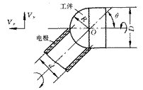
1 Introduction With the advancement of EDM technology, more and more EDM new processes are continuously applied to actual production. Spherical surface forming into electric discharge machining method is a rotary electrode electric discharge machining method which has been gradually developed in recent years. The processing principle is shown in Figure 1. The tool electrode is clamped on the rotating tool spindle. The tool spindle can be adjusted to an angle θ with the X axis in the XOY plane by the CNC rotary table, and the workpiece is clamped on the rotating workpiece spindle, and the workpiece spindle is fixed at XY. On the CNC table, you can move and feed in the X and Y directions. When machining, the spherical part can be machined by ensuring that the tool spindle axis and the workpiece spindle axis remain at the same angle θ. In Fig. 1, the diameter of the workpiece is D, the diameter of the tool electrode barrel is d (radius is r), and the radius of the spherical surface to be processed is R. From the geometric relationship, R, D and d should satisfy  With the relationship of D = 2dcos θ, the required spherical parts can be processed.

Figure 1 Schematic diagram of the spherical electrode forming into a spherical surface
The basic principle of this EDM method is relatively easy to master, and the equipment used is not very complicated. Therefore, it has been applied in production. In order to further explore the general law of spherical surface forming EDM, and broaden the process range of this processing method, this paper proposes a computer simulation technology for spherical surface forming EDM, and has carried out a lot of research work. The motion law of spherical expansion into EDM is analyzed systematically, and the corresponding general mathematical model is established. Using these mathematical models as simulation models, a large number of graphical simulation programs were compiled, and the ideal simulation results were obtained. It lays the foundation for the EDM process of spherical parts and the establishment of CAD, CAPP and CAM systems for rotary electrode EDM.
2 Spherical surface analysis of the motion law of the EDM system 2.1 Spherical surface EDM machining analysis In order to meet the requirements of spherical machining, the spherical surface EDM system (shown in Figure 2) should have the following types of motion: 1) Spindle rotation motion of the cylindrical tool electrode with a diameter d and radius r (angular velocity is ω1); (2) Spindle rotation motion of the workpiece with diameter D (angular velocity is ω2); (3) Adjusting the intersection angle to θ The indexing movement of the tool electrode spindle (angular velocity is ω3); (4) the feed motion of the main table of the workpiece in the X-axis direction (speed is Vx); (5) the advancement of the Y-axis direction of the main table that drives the workpiece Give exercise (speed is Vy).

Figure 2 Spherical surface of the EDM system
Here, the rotary motion of the workpiece spindle and the tool electrode spindle can meet the requirements of the development motion. The direction of rotation of the two axes can be either in the same direction or in the opposite direction, depending on the specific processing conditions. During the machining process, the direction and speed of rotation of the tool spindle and the workpiece spindle can be controlled to minimize electrode loss for the best spherical surface finish.
The indexing rotary motion of the tool electrode spindle can meet the processing requirements of spherical parts with different curvature radii. The indexing range, that is, the angle of rotation, is -90° to +90°. Therefore, the super hemisphere with the smallest radius of curvature and the flat part with the largest radius of curvature can be machined.
The feed motion in the X-axis and Y-axis directions satisfies the requirements for compensating for workpiece electrode and tool electrode losses during machining and for ensuring the final dimensions of spherical machining. Through the feed motion of the X and Y axes, the correct position of the workpiece in the machining system can also be adjusted, and the numerical control functions of the X and Y axes can be fully utilized to improve the mounting accuracy of the workpiece.
Alumininm formwork systems
The light weight aluminum shoring system provides safe, reliable and high load bearing capacity, ample construction working spacing, simple operation, minimize labor, storage and transportation cost. The system can be utilized together with the unique [LEADER" Tubular GN50 Aluminum Scaffolding System to obtain best performance with highest in the construction industry.
Aluminium Formwork System, Aluminium Formwork, Metal Formwork Systems
Anping County ShunXing Hardware Wire Mesh Co., Ltd. , http://www.shunxing-fence.com