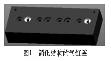
Figure 1 shows the simplified structure of the cylinder head. This part is a very important part of a unit L4R01 diesel engine. The process requires two white f 45mm holes that are highlighted in white by the hinge. The subsequent processing needs to be It is prepared as two positioning pin holes. For this purpose, a set of clamps for the reaming holes must be designed first. The matching relationship between the inner diameter of the guide sleeve and the diameter of the cutter, the outer diameter of the guide sleeve and the cooperation of the template are required. High, if the "bottom-up" design method is used to design each part separately, it is inevitable that the assembly surface will be poorly fitted during assembly, or when the hole on the product is adjusted, the related guide The sleeves on the sleeve and the template need to be redrawn. On the other hand, the unit has more than 100 different types of diesel engines of different sizes. The spacing between the two positioning pin holes and the aperture are different, but their fixture structure is very similar. If the parts of different sizes are repeated one by one, It takes up a lot of design time for designers. At this time, the "top-down" design method should be used. After a complete fixture design is completed, another set of similar structure fixtures will be completed by modifying several parameters.
1. The three-dimensional design of the L4R01 cylinder head reaming fixture is a design method and a management tool for the entire product design process.
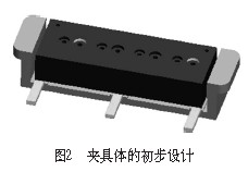
(1) Top-down design, first design the top-level product structure, such as the overall shape of the product or the composition of each part; then transfer the product structure to each part or part by a certain method; finally, Complete the design of the parts based on the product structure passed down from the top. As shown in Fig. 2, in the design process of this set of fixtures, firstly, under the component module of Pro/E, the offset tool button in Pro/E is selected according to the outer dimensions of the cylinder block, and the overall shape of the clip is designed. Fit the face and screw hole position, then pass this model to each part model to get the final part model. The following uses the "Boundary" button to create the shape of the template based on the specific shape of the clip. The boundary positions of 190mm and 740mm are determined to be consistent with the clip. By offsetting the tool button, the two f 45mm hole boundaries on the cylinder block are used. For the reference, the unilateral offset is 10 mm, and the position and size of the two f 65H7 of the boring guide sleeve hole on the template are determined (see Fig. 3).
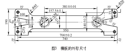
In the same way, under Pro/E's component module, "Insert" → "Component" → "Create New Part", create a guide sleeve with the rotation feature, and use the "Use Boundary" button to make 2 f 65H7 holes on the template. The edge of the guide is used as a reference, and the shape of the guide sleeve is created. After the wall thickness of the guide sleeve is determined, the size of the inner hole can be determined; and then the inner hole size of the guide sleeve is used as a reference to create the hole required for machining the hole on the cylinder head of the workpiece. Locating pin and outer diameter of the inlet reamer. In the top-down design, the underlying part data is controlled by the structure of the top layer, especially the surfaces that need to be matched to each other, and the shape can be precisely controlled. In the above design process, the total length and total height of the clip are controlled by the total height of the cylinder head; the total length and width of the template are controlled by the total length and width of the clip, and the size of the two f 65H7 holes on the template. The position is controlled by the position of the two f 45mm holes on the cylinder block; the outer diameter of the guide sleeve and the template is controlled by the size of the f 65H7 hole on the template;
Valves Series,Check Valve ,Globe Valve ,Butterfly Valve
Plastic Tube, Pipe & Hose Co., Ltd. , http://www.hydraulic-couplings.com