1 Overview
It is difficult to make the welding of the tower furnace steel structure. Who can solve the technical difficulty proves that his technical ability and market share are large. Our company has accumulated experiments on the steel auxiliary frame production and welding process of the power plant. A large amount of technical information and experience to continuously improve product quality in production. Figure 1 shows the overall structure of the tower furnace auxiliary steel frame.

figure 1
2. Tower furnace structure
The 1000MW unit consists of two parts: the main steel frame of the tower furnace and the steel frame of the top. The main steel frame is the main force structure of the boiler. It is a cylindrical frame with a height of 113.2m and a total of five layers. It consists of 4 columns, 20 main beams and 40 diagonal braces.
(1) Each column of the column is divided into 8 sections (1st layer 2nd stage, 2nd layer 2nd section, 3rd layer 1st section, 4th layer 2nd section, 5th layer 1st section), totaling 32 sections, each section is about 16m, each section weighs about 80t, the lower section size is 2500mm×2500mm×45mm; the upper section has a minimum dimension of 2000mm×1700mm×45mm; there are multiple partitions in the horizontal direction of the column; 8 T-shaped stiffeners in the longitudinal direction; two ladders; The upper and lower columns are bolted through the frame flanges at both ends, and the four main fillet welds are partially penetrated welds, and a 10 mm fillet weld is welded on the inside of the lead weld.
(2) 4 layers of each layer of the main beam, the cross-sectional dimension is 2000mm × 900mm × 30mm × 40mm; the length of the diagonal bracing steel plate is 28m and weighs about 75t.
(3) Each of the 8 layers of the diagonal bracing section has a cross-sectional dimension of 1200 mm × 900 mm × 30 mm × 35 mm / 40 mm; a length of 22 m and a weight of about 30 t. The single layer overall structure is shown in Figure 2.
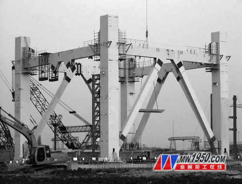
figure 2
The column is box-shaped, with a section size of 2500mm×2500mm, a length of about 16m, a web and a wing plate thickness of 45mm, four main fillet welds are semi-melt welds in the groove, and the weld fillet weld height on the inside of the box 10mm wide, the adjacent two plates of the column have a group of holes connected to the main beam, and the inner wall of the column has a "well"-shaped reinforcing structure, and the inside of the column has 5 layers of partitions at different elevations (excluding the platform) Plate), two T-shaped reinforced steel plates are installed in the longitudinal direction of the wing plate and the web. The thickness of the upper and lower end flange plates of the column is 35mm (end milling plane), the T-shaped reinforcing steel plate and the partition plates H, E, M, B is a penetration fillet weld.
3. Steel column fabrication and welding difficulties
The auxiliary steel frame is large in volume, thick in steel plate and strong in rigidity, and the welding deformation is difficult to control. The overall dimensional accuracy of the column members is high (see Table 1).
Table 1

(1) The large cross-section of the box-type column and the complicated structure of the thick plate are particularly important. There are many weld beads, and the welding operation is a little careless, which is easy to produce defects, resulting in unqualified flaw detection. There are 5 layers of reinforcing partitions and main body in the column body, which have penetration welds, semi-fusion welds and fillet welds. The welding workload is large, the welding conditions are poor, and the welding technique is difficult. The welding of this project mainly uses submerged arc welding with high welding efficiency and good process performance, and CO2 gas shielded welding (flux cored wire, solid cored wire). All penetration welds and semi-through penetration welds are 100% UT flaw detection.
(2) Box-type steel steel various steel plates have national standard Q345B, American standard A572Gr50, plate thickness 45mm, although the steel plate is the same steel number, but from the chemical composition point of view, compared with the national standard, the carbon content is high, the welding should pay attention to welding It must be preheated before, and heat treatment must be carried out after welding. If the welder is slightly negligent in operation, welding cracks may occur. For the box web, the wing plate, the transverse partition and the longitudinal stiffening plate, the assembly precision of the interconnection is high, and the intricate welding deformation is large, and the key technology is to prevent the distortion of the box column. The main factors that cause deformation are assembly size, accuracy, clearance, welding parameters, welding sequence and welder operation awareness, etc., which will lead to welding shrinkage restraint, welding stress, and excessive deformation of the box column. The box column itself has high rigidity and is difficult to correct after deformation, which brings considerable challenges to the production and welding deformation control. In order to ensure the welding quality of the box column and the accuracy of the dimensions of the welded parts, we guarantee the position of the welding groove, the angle, the blunt edge, the welding sequence, and the reasonable welding procedure qualification and assembly sequence tooling technical measures to ensure that the box column After the completion of the beam production, inspection and measurement shall be carried out to ensure that the components are qualified once at the factory. The column body is shown in Figure 3. The various joint forms of the column are shown in Figure 4.
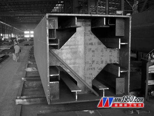
image 3
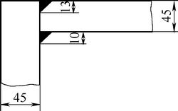
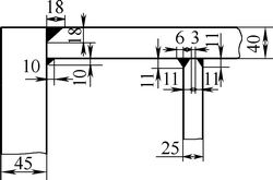

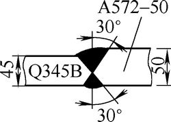
Figure 4 column various joint forms
4. Steel auxiliary frame steel and welding test
(1) The steel is made of national standard Q345B and American standard A572Gr50. The chemical composition and mechanical properties are shown in Table 2.
Table 2 Mechanical properties and chemical composition of different plate thicknesses
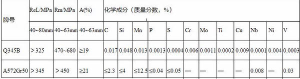
Chart 2 shows that the American Standard A572Gr50 and the national standard Q345B material are basically of the same type of mechanical properties and chemical composition. Before the project started, the welding materials matched with Q345B steel were used for submerged arc welding and CO2 gas shielded welding. The welding procedure qualification test of the method, the pre-heating of the test plate before welding, the proper control of the inter-pass welding temperature during the welding process, and the post-weld heat treatment at 630 ° C after welding, after UT100% flaw detection, the mechanical test fully conforms to the United States. AWS-D1.1 standard. The mechanical properties of the welding process are evaluated as shown in Table 3.
Table 3 Welding process evaluation physical data

(2) Submerged arc welding wire using iron anchor H10Mn2, flux using Yulin SJ101/F48A2, welding equipment using Tangshan Matsushita Group ZD5-1250, as shown in Figure 5, welding parameters are shown in Table 4.
(a) (b)
Figure 5
Table 4 Submerged arc welding parameters

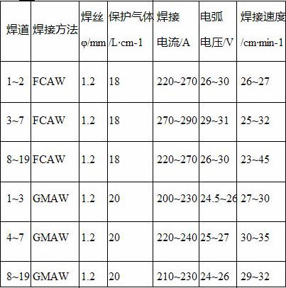
(3) For the welding of CO2 gas, the welding wire is made of Wuhan iron anchor cored wire YCJ501-1, solid wire WH50-6, and the welding machine uses Tangshan Panasonic KRII500.
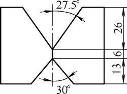
Figure 6 shows the groove form and welding sequence. The welding parameters are shown in Table 5.
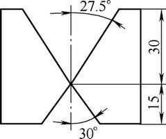
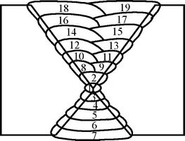
(a) Groove form (b) FCAW
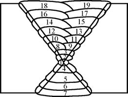
(c) GMAW
Image 6
Table 5 CO2 gas shielded welding parameters
5. Box column fabrication and welding
The most important technical requirement for the welding of box-type column webs and wing plates, the welding of thick plates is that the preparation work before welding must be done well, such as soldering, baking of welding rods, heating and dehumidification of gas, cleaning and polishing of weld bead, before welding. Preheating, interlayer temperature control during welding, slag cleaning in the weld bead, and crystals of silicon oxide and manganese oxide on the surface of the CO2 gas shielded weld will affect the internal quality of the weld. Because the thick plate is not only difficult to repair if it is repaired by defective welding, but also laborious and time consuming, it is necessary to strictly control the quality of the welding.
(1) Assembling the plane projection size of the steel column on the ground, the outline of the steel column, the center line and the end position line, and making the platform tire frame. When setting up the platform, it is necessary to consider the width of the spreader when the component is turned over for easy operation. The final retest of the elevation of the tire frame is ensured at the same horizontal line. Assembling the qualified CNC-cut bottom plate to hang the tire frame, draw the center line, the balance lines at both ends, and strengthen the positioning center and position line of the board, and align the center of the bottom plate with the center line of the ground. Small-stack assembly welding must be done first. After the flaw detection is passed, the level is leveled, and then the bottom plate is closely attached, and then the bottom plate is accurately positioned and welded around the whole surface. After the welding is processed, the positioning line of the partition plate, the end plate and the T-shaped rib is drawn as the installation reference line. The spacer scribe line is based on the bottom plate. The T-shaped rib is based on the center line of the body, and the scribe line is performed with a theoretical length plus a welding shrinkage margin. The qualified T-shaped ribs which are corrected after welding are hung on the bottom plate and positioned according to the drawn positioning line. The spot welding can be located from the middle of the component, and the vertical degree can be added to the auxiliary support to reduce the welding deformation. The T-shaped rib end is easy to open the groove. Welded through the diaphragm. ≥25mm board must be preheated regardless of the butt joint and corner joint, and it can be welded after meeting the requirements. The bottom plate is shown in Figure 7.
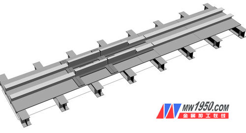
Figure 7
(2) The assembled partition plate is cut by CNC cutting, and the free edge is required to be smoothed to ensure that the partition is closely attached to the web and the wing to control the section size. After the NC plate is finished, the end plates are assembled into a frame, leveled after welding, and the cross-section and diagonal dimensions are measured to ensure that the four corners are 90°. The end plate is opened on all sides and the cross center line and the threaded hole position line are drawn on the frame. The column connection flange requires stacking drill, the bottom end plate pin hole is provided with countersunk bolt hole, and the end plate is assembled when the end plate is assembled. The center of the cross is the same as the center line of the bottom plate, the balance line of the end plate is aligned with the installation position line, the verticality between the end line and the bottom plate is controlled, and auxiliary support is added on both sides of the thickness of the T-shaped rib wing to prevent the T-shaped rib from being welded. The end plate is pulled and deformed. The bottom plate is shown in Figure 8.
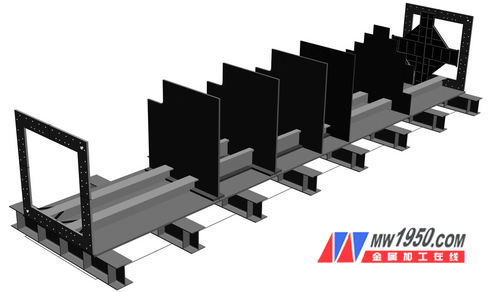
Figure 8
(3) Web assembly According to the above method, the web panel and the T-shaped rib are closed, and the lifting code is installed. When positioning, the center line of the end of the web is aligned with the center line of the end plate so that it is flush with the bottom plate. Adhere to the partition and ensure the support with the overall verticality. Then install the left and right webs in order to control the diagonal ≠3mm for positioning welding. For every 400mm spacing of the tack welding, the length of the weld is 30~40mm. After the assembly, the groove type should be pre-accepted and welded. To ensure the size of the component to control the welding deformation, firstly weld the partition and the web, preferably the two sides are symmetrically welded. . After the completion of the welded web and the floor fillet weld, pay attention to the symmetry of the two sides of the web, and at the same time from the center to the two sides of the weld, at least 4 welders, after welding, the longitudinal T-shaped plate and the separator penetrate the fillet weld, and then Weld the bottom plate and the fillet weld of the partition. The bottom plate and the web are as shown in FIG.


(a) the bottom plate (b) the web
Figure 9
(4) When assembling and assembling the cover plate, align the center line of the end and the cross center line of the end plate for positioning and fixing. After re-measuring the size of the box column, the symmetry of the upper and lower center lines, the verticality, etc., the sides of the four main welds are 100mm. Pre-weld preheating (electric heating or flame heating). The electric heating is recorded by the automatic temperature controller. The flame heating should be measured by a special thermometer at the center of the groove at 75 mm on both sides. The temperature is set at 60~70 °C, and the welding is carried out according to the requirements. Since the four main welds of the box-type column member have not been welded yet, the turning will be deformed, so the welding of the cover plate and the web adopts a horizontal welding station, considering the use of CO2 flux-cored wire protection welding with small welding heat input and small welding deformation. Four welders were welded on both sides from the center to the two sides to complete four main welds. After multiple layers of welding to the surface layer 2~3mm, they turned over 90° and covered with submerged arc welding; then turned over 180°, then welded another On one side, both sides are welded by submerged arc welding at the same time, so that the deformation of the member is smaller.
(5) After face milling, flaw detection, correction, and measurement, the center line of the length is drawn on all four sides, the end milling allowance line is drawn at both ends, and the matching line is controlled. The distance of the matching line is 200mm, and the matching line is the remaining line. It is perpendicular to the centerline and tested, then the upper end mill. Before the milling, adjust the centerline level to within ±1mm, measure the verticality of the power head, and control the distance between the power head surface and the residual line to ensure that the end face perpendicularity and the component length are within the tolerance range.
(6) Drill holes on the column to find the installation position of the beam end plate, fix the end plate and the column, and draw the position line of the hole group. When scribe, the horizontal direction is based on the center line of the column bottom plate, and the longitudinal direction is based on the center line of the column. Drilling and drilling holes with the end plate. Before positioning the beam end plate and the column, the upper and lower parts of the end plate must be flattened and tightened with a clamp, as shown in Figure 10.

Figure 10
6. Conclusion
The box type column is inspected for VT appearance and welding size and 100% UT inspection according to GB50205-2001 standard. The structure size is checked one by one according to the contents of Table 1. The production quality is in full compliance with the predetermined technical requirements. Due to the strict control of the assembly and welding process, the deformation of the box-type column structure is effectively controlled. In addition, the use of beam plate and column hole stack drill can effectively control the hole hole deviation through hole rate of 100%, which makes the company take a big step in the production of auxiliary steel frame of the power plant, ensuring that the auxiliary steel frame is once in the field. Successful installation.
Forever Chemical is a rapidly growing chemical manufacturing & marketing company and has been active in the development, production and marketing of speciality chemicals additive for various applications, since the year 2005.
Forever Chemical contributes substantially to the priority areas of energy conservation and environment protection and has been certified with NS-EN ISO 14001:2004 (EMS) certification.


Forever Chemical is a public limited organization registered under Company`s Act 1956. The quality management system is certified by ISO 9001:2008 certification and has obtained CRISIL verified certification.
In recent years, we are continuously make breakthroughs on Hydrazine Hydrate product and high value-added products. Hydrazine hydrate 80% takes a new vitality to our company. Hydrazine hydrate 100% development is successful. We own mature sector collaboration system, including marketing research department, sales group, and technical team. They work according to their functions and roles. They analyze hydrazine hydrate 55% from all angles. Hydrazine hydrate 64%quality is kept improving all the time.


Hydrazine Hydrate 55%
Hydrazine Hydrate 55%,Dyestuff Intermediates Hydrazine Hydrate,Pharmaceutical Intermediates Hydrazine Hydrate,Oxygen Scavenger Hydrazine Hydrate
Jinan Forever Chemical Co., Ltd. , http://www.jinanforever.com