Abstract Carbon fiber composite (CFRP) has the advantages of high strength, high rigidity, good fatigue resistance and corrosion resistance. It has been widely used in high-end equipment manufacturing such as aerospace and defense military. Aircraft wing, tail and tail cone, rocket exhaust body, engine and booster...
Carbon fiber composite (CFRP) has the advantages of high strength, high rigidity, good fatigue resistance and corrosion resistance, and has been widely used in high-end equipment manufacturing fields such as aerospace and defense military. Aircraft wing, vertical tail and tail cone, rocket exhaust vertebral body, engine and booster housing, artificial satellite bearing structure, solar cell substrate, complex curved antenna and connecting frame, etc. The carbon fiber composite material is used for the panel and the support member. Carbon fiber composites can be used up to 50% on military aircraft and 50% on civilian large passenger aircraft. The amount of composite materials has become one of the indicators for measuring the advancement of aerospace products.
Structural members such as civil aircraft wing beams, purlins and skins are usually composed of carbon fiber composites of various compositions. Carbon fiber composite structural members are usually assembled with titanium alloy and aluminum alloy parts as load bearing supports (framework or bracket) to form composite/alloy (C/A, Composites/Alloy) laminated members, C/A The laminated member mainly adopts a mechanical connection form of riveting and screwing, and a large number of connecting holes are required for assembly. The F-22 fighter has more than 14,000 connection holes per wing and a Boeing 747 with more than 3 million connection holes. CFRP and C/A laminated holes have become extremely important processing steps in aircraft manufacturing.
Fig. 1 Hole defect of carbon fiber composite material The processing precision and quality of the connection hole are the key to ensure the reliability and life of the component connection. Aircraft carbon fiber composite structural parts have a large number of holes, high difficulty, high requirements, heavy work, higher precision and quality requirements for assembly holes, and new challenges for hole making technology, and special high-performance hole making tools are needed. High-efficiency precision hole making process.
The main problems of CFRP hole making The problem of the hole in the carbon fiber composite material of aircraft structural parts is mainly reflected in the following aspects.
The precision and quality of the hole are poor, and the processing defects are serious. If CFRP and C/A laminated holes are made using a conventional twist drill, the drilling accuracy and surface quality are poor. In particular, the axial cutting force during drilling is large, resulting in defects such as fiber array distortion, tearing, interlayer delamination and exit burrs of the carbon fiber composite material, as shown in FIG. Aluminum alloys, titanium alloys, etc., are also easy to form severe exit burrs because they are made of thin plates.
The hole making process is long. Due to the lack of suitable special high-performance tools for CFRP and C/A lamination, in order to ensure the accuracy and quality of the C/A lamination structure, the production site has to adopt "drilling-reaming-rough reaming- The reaming hole-armpit multi-process processing strategy results in many processes and tools, high cost, long process flow, complicated management, and difficulty in automation. This is because when the multi-step processing is performed by using a hand tool, the hole making efficiency is extremely low, and the stability of the hole making and the stability of the quality are difficult to ensure.
The tool wear is severe. Due to the high hardness and high strength of carbon fiber composites, the rapid wear of the tool not only affects the machining accuracy and surface quality, but also keeps the production cost high.
Process parameter matching is difficult. When C/A laminated holes are made, due to the great difference in properties and workability of carbon fiber composites and alloy materials, improper matching and control of drilling process parameters can lead to serious interface defects and exit and inlet defects.
The hole removal process is not smooth and the heat is seriously affected. When making holes in C/A laminated structure, especially when CFRP/Ti alloy is laminated, the drilling alloy will produce continuous high-temperature chips, which is not only easy to chip, and it is easy to scratch or burn the composite material when the high-temperature chips are discharged. The surface of the hole affects the quality of the hole.
In summary, the CFRP and C/A laminated members are greatly different from the traditional metal holes. The special high-performance hole making tools and high-efficiency precision hole making technology have become the key technologies in the assembly of composite materials in the aerospace industry. .
Performance requirements of carbon fiber composite hole making tools The types of tool structures used in carbon fiber composite holes are complex, including Twist drill, One shot drill reamer, Multi-facet drill, Kevlar drill, Core drill, etc. Through the optimization of the tip shape and the tool angle, the carbon fiber cutting is smoother and smoother when drilling the carbon fiber composite material, so that the smaller axial force, the lower drilling temperature and the higher quality hole are the tool matching. The main goal of performance research.
In the processing of carbon fiber composites, the transverse blade of the large negative rake angle is liable to cause excessive axial force and may cause delamination. Therefore, the X- or S-type cross-edge grinding method is usually used to change the chisel edge. The dagger drill is strictly a kind of drill and hinge compound tool. Because the circumferential side edge is directly involved in the drilling as the main cutting edge, it is easier to form a burr-free, high-quality surface. The role of the dagger in inhibiting burr growth has been confirmed in many researchers' experimental studies. The application of multi-face drilling in carbon fiber composite drilling is derived from the successful use of octahedron by Lockheed in the United States to improve the quality of the hole and the durability of the tool. The three-point drill is designed with two protruding sharp edges at the turning point of the outer edge of the drill. It is specially used for cutting the fibers to prevent burrs and tearing of the holes. Although the three-point drill can effectively control the burr of the orifice, the strength of the main cutting edge is also weakened. Table 1 is the type of tool currently used in the research of carbon fiber composite drilling.
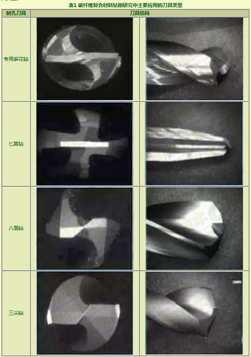
Table 1 Tool type hole cutter tool structure mainly used in carbon fiber composite drilling research
In the processing of carbon fiber composite materials, PCD or diamond coated cemented carbide is commonly used in tool materials. At present, diamond-coated cemented carbide tools have become the key technology to solve the special tool wear and short tool life of carbon fiber composite materials.
Experimental study on carbon fiber composite hole making tool The material used in this test is a multi-directional laminated carbon fiber composite laminate, each layer is a unidirectional single layer, and the laminate layer has a total of 32 layers. The sheet size is 300mm × 200mm × 6mm, as shown in Figure 2. The test tool involves a diamond-coated cemented carbide multi-face drill and a cemented carbide dagger drill in the structural form, as shown in Fig. 3, and the cutter diameter is 6.35 mm. The test was carried out on a DMG DMU70V CNC machining center. The cutting force and torque were measured using a KISTLER 9129AA piezoelectric dynamometer and a KISTLER 5070 charge amplifier. The KEYENCE VHX-600 ultra-depth microscope was used to detect tool wear and observe the hole shape. And burr conditions.
Experimental study on carbon fiber composite hole making tool The material used in this test is a multi-directional laminated carbon fiber composite laminate, each layer is a unidirectional single layer, and the laminate layer has a total of 32 layers. The sheet size is 300mm × 200mm × 6mm, as shown in Figure 2. The test tool involves a diamond-coated cemented carbide multi-face drill and a cemented carbide dagger drill in the structural form, as shown in Fig. 3, and the cutter diameter is 6.35 mm. The test was carried out on a DMG DMU70V CNC machining center. The cutting force and torque were measured using a KISTLER 9129AA piezoelectric dynamometer and a KISTLER 5070 charge amplifier. The KEYENCE VHX-600 ultra-depth microscope was used to detect tool wear and observe the hole shape. And burr conditions.
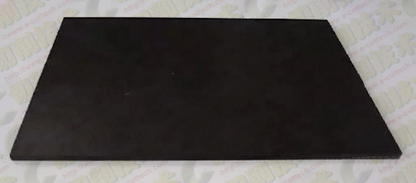
Figure 2 Multi-directional ply carbon fiber composite laminate for testing
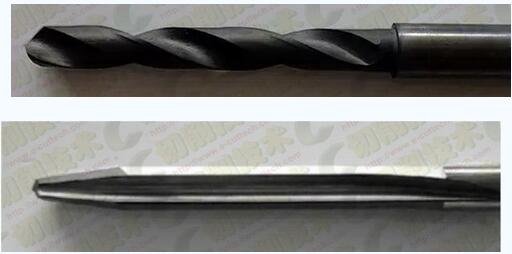
Figure 3 test tool diamond coated carbide multi-faceted drill
(above: drilling with carbide drill; bottom: analysis of test results)
Figure 3 test tool diamond coated carbide multi-faceted drill
(above: drilling with carbide drill; bottom: analysis of test results)
(1) Diamond coated cemented carbide multi-faceted drill Table 2 shows the results of the hole making test of the diamond coated cemented carbide faceted drill. High rotational speed and low feed can achieve smaller axial forces for drilling, which helps to avoid delamination and burr formation in carbon fiber composites. Therefore, a small axial force can be obtained by using the processing parameters in the table, the rotational speed of 10,000 rpm, the feed speed of 40 mm/min, or the rotational speed of 8000 rpm and the feed speed of 80 mm/min.
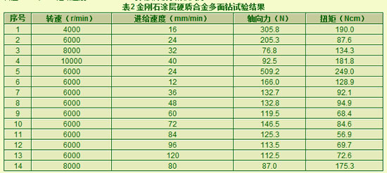
Table 2 Diamond coated cemented carbide multi-face drilling test
Under the above parameters, the shape of the hole is shown in Table 3. Both parameters obtained good hole exit quality and inlet quality. Considering the hole making efficiency, the speed of 8000 rpm and the feed rate of 80 mm/min were preferred as the parameters of diamond coated cemented carbide multi-face drilling.
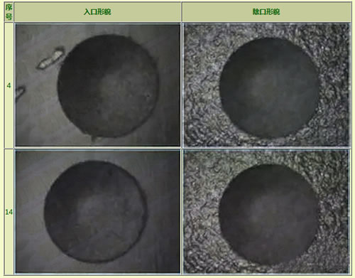
Table 3 Diamond coated cemented carbide multi-faceted drilled hole shape No. Entrance shape except mouth shape
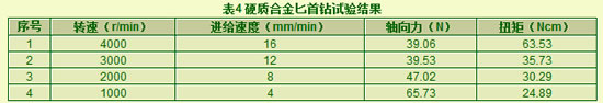
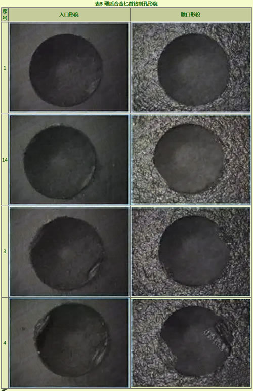
(2) Carbide Dagger Drill Table 4 shows the results of the hole making test of the cemented carbide dagger. The first drill is suitable for low speed and small feed machining. High speed will produce high processing temperature and cause carbon fiber composite to burn. Combined with the shape of the hole in Table 5, the processing parameters in the table, the speed of 4000 rpm and the feed rate of 16 mm/min were used as optimized processing parameters.
Cup Kn95 Mask,Kn95 Approved Cup Mask,Kn95 Protective Cup Mask,Kn95 Protective Cup Face Mask
Ningbo Autrends Prevention Products Co., Ltd , https://www.autrendsafety.com