1 Overview
During the charging and vibration process of a product, a 1Cr18Ni9Ti pipe joint leaks from the fillet weld of the pipe. After the repair welding, the charging pressure test is continued, and no leakage occurs at this position, but in another pipe joint and pipe A leak occurred at the fillet weld.
The raw material of the pipe joint in the combined conduit is 1Cr18Ni9Ti hexagonal steel, and the material of the pipe is 1Cr18Ni9Ti cold drawn pipe. Welding process: pipe and pipe joint matching → pickling → welding → strength, airtight → passivation → cleaning → painting → general inspection.
2. Failure analysis
(1) Macroscopic observation The macroscopic morphology of the combined conduit is shown in Figure 1, and cracks are found at the fillet welds of the joint. The crack is in the area enclosed by the black marker in Figure 1. The crack coincides with the weld of the weld, as indicated by the arrow in Figure 1. Visual inspection, there are no macro defects at the corner welds with cracks.

Figure 1 Macro photo of pipe joint fillet weld
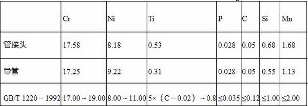
(2) Chemical composition analysis The samples were sampled and analyzed in a 22 mm tube and a 6 mm tube joint, and the chemical compositions thereof are shown in Table 1. The test results show that all the elements of the stainless steel materials used in the combined conduits meet the requirements of GB/T 1220-1992.
Table 1 Chemical composition (mass fraction) of pipe joints and conduits (%)
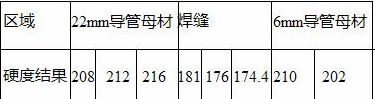
(3) Hardness test Sampling was performed by cutting the pipe joint, fillet weld, and conduit along a plane perpendicular to the 22 mm duct axis, that is, perpendicular to the plane of the crack. The micro-hardness test was performed on the fillet weld and the base metal, and the results are shown in Table 2. As can be seen from Table 2, the hardness of the weld zone is significantly lower than that of the base metal.
Table 2 Hardness test results of welds and base metals (HV)
(4) Metallographic observation A metallographic sample was prepared along a section perpendicular to the surface of the crack. In the weld area that is in contact with the 22 mm duct, a clear weld line can be seen from the weld and the vicinity where cracking has never occurred, as indicated by the arrows in FIG. The boundary between the fusion line and the outer surface is substantially coincident with the solder fillet, and is close to the side of the base material. From the weld to the heat-affected zone, to the base metal, the structure changes continuously, and no welding defects such as pores and slag inclusions are found. The weld zone on the left side of the weld line is a typical stainless steel welded structure with dendritic ferrite distributed on the austenite matrix. The heat affected zone from the fusion line to the right is austenite grain.

Figure 2 Weld area close to 22mm duct
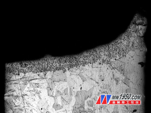
Figure 3 Crack propagation path and tissue near the crack 
Figure 4 Fatigue strips in the fracture
By observing the weld area where the crack occurs, it can be seen that the crack is generated in the weld area, and the distance from the fusion line is 130 to 160 μm, which is substantially parallel to the fusion line, as shown in FIG. The boundary between the crack and the outer surface of the catheter coincides with the solder fillet. The left side surface of the figure is the outer surface of the catheter. The structure around the crack is a dendritic ferrite distributed on the austenite matrix.
(5) Fracture observation Separate the weld along the crack and observe the fracture morphology of the crack surface. A fatigue band can be seen on the surface of the fracture, as shown in Fig. 4, so it is judged that the crack is caused by fatigue fracture. Some steps with a large difference in height were observed on the surface of the fracture.
Looking at the entire fracture surface, it can be seen that the radial ridge line is substantially directed from the outer surface of the catheter to the inner side. Observing the fracture near the outer surface, a plurality of crack sources can be found, as shown in Fig. 5 and Fig. 6, indicating that the fracture has a plurality of fatigue sources. The crack source is generated on the outer surface of the duct and spreads to the inside, and the ridgeline of the radiation can be seen in the crack source region, which is a quasi-cleavage fracture surface. No defects such as holes or slag inclusions were found in the crack source.
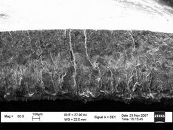

Figure 5 Topography of the fracture
3 Discussion
From the appearance and fluorescence test results, the crack was generated at the fillet weld of the pipe and the pipe joint, and the crack coincided with the weld bead at the weld bead near the 22 mm pipe.
The observation of the crack fracture morphology shows that there is a significant fatigue band in the fracture, and the width of the strip is about 2 μm, indicating that the crack is caused by fatigue fracture. The entire fracture has a ridge line with relatively large undulations, and the end region of the fatigue crack growth is fan-shaped. The center of the sector is directed toward the outer surface of the fracture weld, and the source region of the fatigue crack is near the outer surface of the weld or the vicinity. A magnified observation of the fracture near the outer surface allows observation of multiple sources of fatigue cracks, which are generated on the outer surface, as shown in FIG. No material and weld defects were observed near the crack source, and fatigue cracks were generated at the surface of the weld bead, which was a normal fatigue fracture. It shows that during the vibration process, the stress level of the weld exceeds the fatigue limit and fatigue cracking occurs. Analysis from the entire fatigue fracture is a low-cycle fatigue crack.

Figure 6 Fatigue source at the outer surface of the weld
The chemical composition of the conduit fittings meets the requirements and the hardness is between 202 and 216 HV. Only the hardness in the weld zone is low, indicating that the weld is soft, and at the same stress level, the weld will first yield.
Microstructure analysis showed that there were no defects such as pores and inclusions in the weld zone, which was normal weld microstructure. Cracks are generated at the solder fillet and extend along the weld, 130 to 160 μm from the fusion line, as shown in Figure 3. Fatigue cracks are produced at the weld legs where the cross section is the smallest and the hardness is low. It shows that during the vibration process, stress concentration occurs, and fatigue cracks occur in the weaker areas of the weld. As the vibration continues, the fatigue cracks expand and leaks when it extends to the inner surface of the weld.
4. Conclusion
(1) Cracks are caused by fatigue cracking.
(2) Fatigue cracks are generated at the weld legs on the outer surface of the weld and have multiple sources of fatigue.
(3) Fatigue cracking is generated in the weakest part of the weld (near the weld line) and is a normal fatigue fracture.
(4) Fatigue cracking is caused by the stress concentration of the welding feet during the vibration process.
This Multi Fuction Safety Vest is an upgraded version of the base vest, special vests for special industries. Such as flame fuction safety vest benefit from flame retardant reflective tape as well as limited flame spread binding and can protect workers against occasional and brief contact with small igniting flames, in circumstances where there is no significant heat hazard and without the presence of another type of heat. But it is necessary to know that fire resistance is not equal to incombustibility; Waterproof Safety Vest can protect the wearer from getting wet and keep warm.


Multi Fuction Safety Vest
Multi Fuction Safety Vest,Road Safety Vest,Traffic Safety Vest,Police Reflective Vest
Xinxiang Zhongke Reflective Material Co., Ltd. , http://www.zkprotective.com