The spindle of a machine tool is often compared to a human arm, as it plays a crucial role in the overall performance of the machine. The precision and stability of the spindle directly influence the quality and accuracy of the final product. As a result, error testing of machine tool spindles has become an essential part of performance evaluation, fault analysis, and factory quality control. Spindle error testing typically involves several key aspects, such as radial and axial runout measurement, thermal deformation analysis, and static stiffness assessment. This paper introduces a visualization-based spindle error detection system developed using the VTK platform, which integrates both beating detection and thermal deformation monitoring. By creating 3D models of the machine and visualizing the spindle errors, users can gain a comprehensive understanding of how these errors affect the machine's overall behavior. This approach provides a much clearer and more intuitive insight than traditional text descriptions or 2D charts, offering significant value for performance optimization and structural design improvements.
**Spindle Error Test System**
The spindle error test system was developed by the Shenyang Machine Tool (Group) Design and Research Institute. It consists of both hardware and software components. The software is primarily responsible for parameter configuration, channel management, real-time data display, and storage. It is built using C++ for the underlying development and C# for the user interface, ensuring fast response times and an easy-to-use environment. Figure 1 shows the main interface of the system, where most operations—such as adjusting channel colors, setting sampling time, choosing data processing modes, defining display ranges, and controlling laser displacement sensors—can be performed without switching windows. This streamlined design greatly enhances efficiency during actual testing.
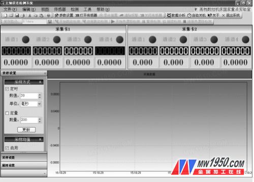
**Figure 1: Data Acquisition Main Interface**
Figure 2 displays the software configuration interface, where users can set hardware parameters and configure channels. All settings are saved in an XML file, which is automatically loaded when the software starts, ensuring consistency and ease of use.
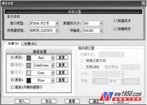
**Figure 2: Data Acquisition Configuration Interface**
The hardware setup includes two IF2004 data acquisition cards from Mi Fu Company, each with four channels, five laser triangular reflection-type displacement sensors (with a measuring range of 24–26 mm), five controllers, one 24V power supply module, and necessary cables and an industrial computer. Figure 3 illustrates the schematic of a single-channel hardware connection.
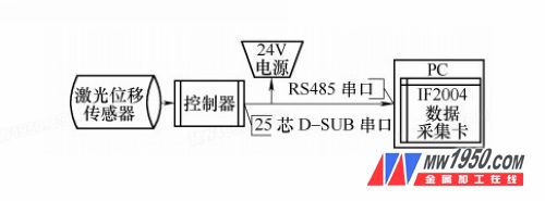
**Figure 3: Schematic of One-Channel Hardware Connection**
With this hardware configuration, the system can simultaneously acquire data from up to five channels at a frequency of 10 kHz per channel. Typically, one spindle axis is measured along with two other directions. The X, Y, and Z axes of the spindle can be monitored simultaneously, and the displacement data can also be used to calculate the radial tilt angle of the spindle through data processing. The specific installation method of the laser displacement sensor is shown in Figure 4.

**Figure 4: Installation Schematic of the Spindle Error Measuring Device**
1. Spindle check rod
2. Laser displacement sensor
3. Bracket
Garden Light,Outdoor Led Garden Lights,Waterproof Garden Light,3M Aluminium Garden Light
Yangzhou Langxu Lighting Technology Co., Ltd , https://www.street-lighting.com