Zhang Zhaoxin, Director of Process Room, Hubei Hangyu Jiatai Aircraft Equipment Co., Ltd.
Model Construction
(1) Base Body Construction: The base body of the integral impeller is created using a wrapping function around a rotating shaft with rotational symmetry. (2) Blade Modeling: The focus of the model construction lies in accurately representing the blade surface. This paper introduces a method that uses the blade midline equation to define control curves for the blade surface. By intercepting the blade's mid-plane with a series of coaxial cylindrical surfaces, a set of mid-surface curves is generated to construct the blade’s mid-plane, ultimately forming the blade surface. Example: Y = 1.272 × 10â»â´ × D × X²·â¶â¶ This equation defines the relationship between Y and X values on the curve. Analysis shows: - The arc angle (a), arc length (L), and coordinates (X, Y, Z) are related as follows: - Y = (D/2) × cos(a) - Z = (D/2) × sin(a) - a = (L/D) × (360/Ï€) The relationship between L and X is given by the midline equation: - L = 1.272 × 10â»â´ × D × X²·â¶â¶ By offsetting the mid-surface, both the pressure and suction surfaces can be obtained. Using boolean operations based on topological relationships, a solid model of the impeller can be constructed.2. Manufacturing Process
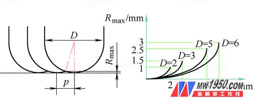
Basic process steps include: 1. Blank manufacturing: Machining the impeller surface. 2. CNC machining: Milling the blade surface, runner surface, and transfer fillet. 3. Dynamic and static balance test: Adjusting the balance by removing material in designated areas based on test results. 4. Surface treatment: Applying anti-corrosion and wear-resistant coatings according to technical specifications. Challenges during processing include: (1) A large twist angle on the blade surface. (2) In this example, the average blade thickness is 1.4 mm, with a maximum overhang of 22 mm. Poor structural rigidity leads to vibration, resulting in issues like undercutting, overcutting, and chattering. This affects dimensional accuracy, shape, and surface quality. (3) Small blade pitch—minimum blade spacing is 2 mm, with a rounded root (R1). Finishing requires f1.5R0.75×3°-L45 taper shank ball-end cutters. These tools have a high aspect ratio, low rigidity, and poor cutting efficiency, making it difficult to ensure machining accuracy and surface finish. Process parameters: (1) For rough machining, key parameters include cutting speed (V), depth of cut (ap), cutting width (ae), and machining allowance. When using a ball-end mill, ap and ae are typically 30% of the tool diameter to maintain a good balance between material removal rate and cutting force. Cutting speed is adjusted based on the impeller material and recommended tool parameters. Usually, 0.3–0.5 mm is left for finishing on the blade and runner surfaces. (2) For finishing, the main parameters are cutting speed (V), radial step (ae), and feed per tooth (fz). The cutting speed is adjusted according to material and tool recommendations, while spindle speed (S) is calculated using V and the effective diameter (De) of the ball-end cutter (see Figure 1).
Figure 1 Ball-cutter actual machining position, effective diameter

Figure 2 Relationship between step p and theoretical maximum residual height Rmax
Fan Light,Ceiling Fan Light,Led Ceiling Lamp Light,Led Ceiling Fan
JIANGMEN MOSCOT OPTOELECTRONIC TECHNOLOGY CO.,LTD. , https://www.sensorsled.com